
Real Time Quantum Error Correction#
Real-time Quantum Error Correction (QEC) is essential to build reliable quantum computers. Up until this point we treated quantum error correction as an algorithmic problem, a QEC decoder receives a syndrome and guesses the most likely error that caused the syndrome. But there are many additional challenges in practical quantum computing.
In a real quantum computer, the decoding cannot wait until all measurement rounds are complete. Instead, the decoding must occur while the quantum computer is running, because the execution of certain gates, such as T-gates, depends on the decoded result of previous syndromes. This requirement gives rise to online decoding (or real-time decoding) where quantum error correction happens while the quantum computer is executing a quantum circuit.
We first look at why we need real time decoding.
Why is real-time decoding necessary?#
If a quantum computation consists only of Clifford gates (such as CNOT and Hadamard), decoding can be deferred until the circuit finishes, and corrections can be applied as a post-processing step. However, not all quantum circuits can be exhaustively described using Clifford gates. Such circuits require non-Clifford gates, such as the T-gate, which introduces a critical dependency on real-time decoding.
The most common way to implement a T-gate is through magic state injection and gate teleportation [1,2]. This circuit is shown in figure 1 taken from [3]. In this example the T gate is first applied to a qubit in \(\vert+\rangle\) state which we measure in Z basis after it interacts with the target qubit via a CNOT gate. Based on this measurement result we apply a conditional S gate on the first qubit. If we think the two qubits as logical qubits then we need to know the decoded result to apply the conditional S gate. If the decoder is slow, the quantum computer will spend valuable time idling, waiting for decoding results instead of progressing with computation.
This feedback loop makes real-time decoding essential. Without it, the latency introduced by waiting for decoding results would severely limit the logical clock speed of the quantum computer, reducing overall performance.
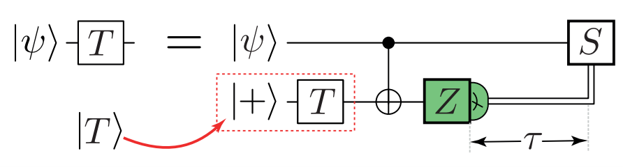
Figure 1: Circuit for T-gate implementation using magic state injection and gate teleportation. The measurement outcome determines whether a conditional S gate is applied, requiring real-time decoding feedback.
Requirements of a real-time Quantum Error Correction#
Real-time decoding introduces stringent performance requirements. Below are the key requirements of a real-time decoder.
Streaming decoding
A real-time decoder must process syndromes as they arrive, rather than waiting for all measurement rounds to complete. One common approach is the sliding window method, where the decoder works on overlapping segments of measurement data. For example, it may decode rounds 0 to 2d–1 and commit the first d rounds, then slide forward to decode rounds d+1 to 3d–1. Figure 2 taken from [3] illustrates sliding window decoding.
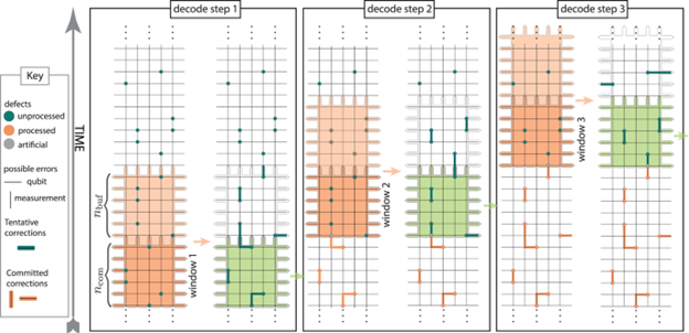
Figure 2: Sliding window decoding processes overlapping segments of syndrome data. The window (orange) slides forward after each commit (green), ensuring decoding while syndrome data arrives
Inverse throughput faster than the rate of measurement
The decoder must process measurements faster than the quantum computer’s measurement rate. If decoding is slower than data generation, a backlog forms —and this backlog grows exponentially with the number of T-gates [4].
Figure 3 illustrates this effect using an example from [5]. Assume at the first T-gate, the decoder needs to process data from \(D\) measurement rounds, which results in response being available after \(fD\) measurement rounds. During this period, the quantum computer continues generating new measurements, which must also be decoded later. If the second T-gate occurs after \(D\) more measurement rounds, the decoder now has to decode not only the new data but also the accumulated backlog, requiring to wait \(f(fD + D)\) measurement rounds until the decoding response is available. This pattern continues and at the \(n^\text{th}\) T-gate the decoding time would be approximately \(f^n D\), leading to an exponential increase in latency with each additional T-gate.
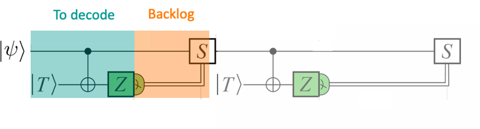
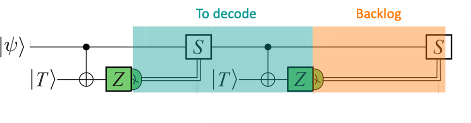
Figure 3: At each T-gate, the decoder must process a growing backlog of measurement data if decoding is slower than the measurement rate.
To avoid this decoding rate must exceed the measurement rate \((f<1)\). For superconducting quantum computers which generate a measurement round every 1 μs, the decoder’s inverse throughput must be less than 1 μs.
Therefore, for real-time quantum error correction a decoder has a stringent requirement, the rate of decoding must be higher than the rate of measurement.
Minimal latency
The latency of the quantum error correction is the time between measurement and the application of the corresponding gate based on the decoder result. This latency determines the logical-clock rate (how fast logical operations can be applied) of the quantum computer, as at every T-gate the quantum computer must wait until the correct gate is determined based on the decoder result.
For superconducting systems, a latency below 10 microseconds is desirable.
To better understand how latency and throughput affect the total execution time of a quantum computation, run this notebook locally and use the interactive Python program below. Adjust the latency and throughput values to see how these changes influence the overall wall-clock time. Note that in the program the compute time is measured using the number of T-gates the code encounters.
Additional desirable features
Beyond the core requirements, there are several other factors desirable for real time quantum error correction.
a. Accuracy : Higher decoding accuracy reduces the need for large error correction codes. For example, to achieve the logical error-rate of \(10^{-15}\) using surface codes, the minimum-weight perfect matching decoder requires a \(d=27\) surface code while the less accurate union-find decoder requires a \(d=29\) surface code [6].
b. Logical Branching : Essential for universal quantum computation involving T-gates.
c. Support for Diverse Error Models : These including handling leakage and erasure errors. A decoder becomes more accurate when it considers additional types of errors.
d. Resource efficiency : This factor is particularly important for hardware-based decoders. A resource efficient decoder can decode more logical qubits using same hardware area, which reduces the cost of decoding as well as latency to transport data from the physical qubit hardware when scaling the decoder to large code distances.
#!/usr/bin/env python3
# -*- coding: utf-8 -*-

import panel as pn
import numpy as np
import matplotlib.pyplot as plt

pn.extension()

def plot_wall_clock_time(latency, throughput):
    """
    Main model:
        y(x) = max( (latency + 1) * x,  x^(1/throughput) )

    Reference:
        y = x  (if decoding results are instantaneously available)
    """
    # X in [0, 100]
    x = np.linspace(0, 100, 500)

    # Component curves
    y_linear = (latency + 1) * x
    # Guard against throughput==0 (shouldn't happen with slider bounds, but be safe)
    exponent = 1.0 / max(throughput, 1e-12)
    y_power = np.power(x, exponent)

    # Main model is elementwise max
    y = np.maximum(y_linear, y_power)

    fig, ax = plt.subplots(figsize=(6, 4))

    # Main curve
    ax.plot(
        x, y,
        color="#1f77b4", linewidth=2.2,
        label=r'Wall clock time with latency {:.1f} and throughput {:.2f}'.format(latency, throughput)
    )

    # Reference dashed line y = x
    ax.plot(
        x, x,
        linestyle="--", color="#656060", linewidth=1.8,
        label='If decoding results are instantaneously available (y=x)'
    )

    # Labels/title
    ax.set_xlabel('Compute Time (no backlog)')
    ax.set_ylabel('Wall Clock Time')
    ax.set_title('Wall Clock Time vs Compute Time')

    # Fixed axis limits
    ax.set_xlim(0, 100)
    ax.set_ylim(0, 500)

    ax.grid(True, alpha=0.3)
    ax.legend(loc="upper left")

    # Annotate the dashed reference line
    ax.text(
        65, 65,
        'if decoding results\nare instantaneously available\n y=x',
        color="#656060", fontsize=9, ha='left', va='bottom',
        bbox=dict(boxstyle="round,pad=0.25", fc="white", ec="#656060", alpha=0.8)
    )

    fig.tight_layout()
    return fig

# Widgets
latency_slider = pn.widgets.FloatSlider(name='Latency', start=0, end=10, step=0.1, value=2)
throughput_slider = pn.widgets.FloatSlider(name='Throughput', start=0.1, end=2, step=0.01, value=1)

# Bind function to widgets
interactive_plot = pn.bind(
    plot_wall_clock_time,
    latency=latency_slider,
    throughput=throughput_slider
)

# Layout (replace MarketText with Markdown)
header = pn.pane.Markdown(
    "## Wall Clock Time Explorer\n"
    "_Main model:_ `y = max((latency+1)·x, x^(1/throughput))`",
    styles={"margin-bottom": "0.5rem"}
)

dashboard = pn.Column(
    header,
    pn.Row(latency_slider, throughput_slider),
    pn.pane.Matplotlib(interactive_plot, tight=True),
    sizing_mode="stretch_width",
    styles={"max-width": "900px", "margin": "0 auto"}
)

if __name__ == "__main__":
    dashboard.show(title="Wall Clock Time Explorer")
Practical Implementation#
Next, we will look at how quantum error correction works in practice.
In a real quantum computer, quantum error correction involves multiple layers of coordination between hardware and software. The process begins with syndrome measurements collected from the physical qubit hardware via the control system. These measurements are then sent to the QEC stack, which performs decoding.
Large-scale quantum computers can have millions of physical qubits, resulting in thousands of logical qubits. A single global decoder cannot handle this complexity. Therefore, we need many small decoders that decode syndromes for specific regions of the quantum processor. We call them local decoders. Each local decoder determines the logical state of its assigned logical qubits and sends the results to a global unit called coordinator or orchestrator.
The orchestrator aggregates these decoded results and decides the next sequence of gates. It then signals the control system to execute the appropriate operations. Figure 4 shows an example stack of a Quantum Computer.
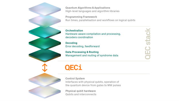
Figure 4: Example Control stack of a quantum computer
From the above paragraph, two things should be straightforward for you now. First the decoding latency is extremely critical, and the decoder must be tightly integrated close to the physical qubit hardware. Second, a single global decoder is not sufficient, and we need hundreds of local decoders coordinating together to run a real-time quantum computer.
We will next look at what are the approaches to achieve that.
Approaches to Achieve Real-Time Decoding#
Achieving real-time quantum error correction requires both algorithmic innovation and architectural development.
Algorithmic innovations
The goal of algorithmic development is to design faster and more resource-efficient algorithms without significantly sacrificing accuracy.
One notable advancement is parallel window decoding [3], introduced by Riverlane, which divides the decoding problem into overlapping windows that can be processed simultaneously, improving throughput for large-scale systems. Lin et al.[7] and Tan et al.[8] proposed similar approaches simultaneously.
Another important approach involves distributed algorithms, such as Helios [9], which implement union-find decoding in a distributed manner, enabling large-scale parallelism. Similarly, techniques like Fusion-Blossom [10] partition minimum-weight perfect matching problem across parallel resources to accelerate computation. For scenarios where speed is critical and significant loss of accuracy is acceptable, greedy algorithms such as NISQ+ [11] offer a practical compromise.
Architectural Choices
Due to the stringent latency requirements, CPUs fail to decode large logical codes fast enough. Therefore, the community has moved to custom hardware choices such as FPGAs, GPUs and ASIC.
FPGAs (Field-Programmable Gate Arrays) have emerged as a popular choice because they provide an ideal balance between flexibility and speed. Researchers have proposed various FPGA based implementations for popular decoding algorithms. These include MicroBlossom [12] for minimum-weight perfect matching, Helios [9], Collision Clustering [13] and LCD [14] for Union-Find, and Relay-BP [15] and Valls et al. [16] for belief propagation based decoders.
ASICs (Application-Specific Integrated Circuits) offer even greater speed and efficiency than FPGAs, making them highly suitable for large-scale systems. However, ASIC development involves significant upfront costs and long design cycles, which have limited their adoption. Riverlane’s Collision Clustering Decoder [13] is one of the first ASIC-based designs for quantum error correction. Other works, such as NISQ+[11] , QECOOL [17], and QULATIS [18] , have proposed ASIC designs using Single Flux Quantum logic.
GPUs (Graphics Processing Units) provide high throughput and are well-suited for certain quantum technologies, such as trapped-ion systems. However, their relatively high latency makes them less attractive for superconducting qubit architectures, where microsecond-level response times are critical.
Finally, networking strategies play an essential role in coordinating local decoders across large-scale quantum processors. Approaches such as Deconet [6] propose network-integrated solutions for rapid communication, while QULATIS [18] explores chip-to-chip connectivity to minimize coordination delays. These strategies are necessary to aggregate the results and act quickly upon, preserving the lifetime of logical qubits.
Additional Reading#
Real-time decoding for fault-tolerant quantum computing: progress, challenges and outlook
Parallel window decoding enables scalable fault tolerant quantum computation
Network-Integrated Decoding System for Real-Time Quantum Error Correction with Lattice Surgery
References#
S. Bravyi & A. Kitaev, “Universal quantum computation with ideal Clifford gates and noisy ancillas,” Phys. Rev. A 71, 022316 (2005). arXiv:quant-ph/0403025
D. Litinski, “A game of surface codes: Large-scale quantum computing with lattice surgery,” Quantum 3, 128 (2019). arXiv:1808.02892
L. Skoric, D. E. Browne, K. M. Barnes, N. I. Gillespie, & E. T. Campbell, “Parallel window decoding enables scalable fault tolerant quantum computation,” Nature Communications (2023). arXiv:2209.08552
B. M. Terhal, “Quantum error correction for quantum memories,” Rev. Mod. Phys. 87, 307–346 (2015). arXiv:1302.3428
Riverlane, “Why do we need real-time quantum error correction?” (2023). riverlane.com
N. Liyanage, Y. Wu, E. Houghton, & L. Zhong, “Network-Integrated Decoding System for Real-Time Quantum Error Correction with Lattice Surgery,” arXiv:2504.11805 (2024). arXiv:2504.11805
S. F. Lin, E. C. Peterson, K. Sankar, & P. Sivarajah, “Spatially parallel decoding for multi-qubit lattice surgery,” arXiv:2403.01353 (2024). arXiv:2403.01353
X. Tan, F. Zhang, R. Chao, Y. Shi, & J. Chen, “Scalable surface code decoders with parallelization in time,” PRX Quantum (2022). arXiv:2209.09219
N. Liyanage, Y. Wu, A. Deters, & L. Zhong, “Scalable quantum error correction for surface codes using FPGA,” in Proc. IEEE Int. Conf. Quantum Computing & Engineering (QCE), 2023. arXiv:2301.08419
Y. Wu & L. Zhong, “Fusion Blossom: Fast MWPM decoders for QEC,” in 2023 IEEE International Conference on Quantum Computing and Engineering (QCE), 2023. arXiv:2305.08307
A. Holmes, M. R. Jokar, G. Pasandi, Y. Ding, M. Pedram, & F. T. Chong, “NISQ+: Boosting quantum computing power by approximating quantum error correction,” in Proc. ACM/IEEE Int. Symp. Computer Architecture (ISCA), 2020. arXiv:2004.04794
Y. Wu, N. Liyanage, & L. Zhong, “Micro Blossom: Accelerated minimum-weight perfect matching decoding for quantum error correction,” in Proc. ACM Int. Conf. Architectural Support for Programming Languages & Operating Systems (ASPLOS), 2025. arXiv:2502.14787
B. Barber, K. M. Barnes, T. Bialas, O. Bugdaycı, E. T. Campbell, N. I. Gillespie, K. Johar, R. Rajan, A. W. Richardson, L. Skoric, C. Topal, M. L. Turner, & A. B. Ziad, “A real-time, scalable, fast and resource efficient decoder for a quantum computer,” Nature Electronics 8, 1 (2025). arXiv:2309.05558
A. B. Ziad, A. Zalawadiya, C. Topal, J. Camps, G. P. Geher, M. P. Stafford, & M. L. Turner, “Local clustering decoder: a fast and adaptive hardware decoder for the surface code,” arXiv:2411.10343 (2024). arXiv:2411.10343
T. Maurer, M. Bühler, M. Kröner, F. Haverkamp, T. Müller, D. Vandeth, & B. R. Johnson, “Real-time decoding of the gross code memory with FPGAs,” arXiv:2510.21600 (2025). arXiv:2510.21600
J. Valls, F. Garcia-Herrero, N. Raveendran, & B. Vasić, “Syndrome-Based Min-Sum vs OSD-0 Decoders: FPGA Implementation and Analysis for Quantum LDPC Codes,” in Proc. IEEE Int. Symp. Information Theory (ISIT), 2021. IEEE Xplore
Y. Ueno, M. Kondo, M. Tanaka, Y. Suzuki, & Y. Tabuchi, “QECOOL: On-Line Quantum Error Correction with a Superconducting Decoder for Surface Code,” in IEEE/ACM Design Automation Conference (DAC), 2021. arXiv:2103.14209
Y. Ueno, M. Kondo, M. Tanaka, Y. Suzuki, & Y. Tabuchi, “QULATIS: A quantum error correction methodology toward lattice surgery,” in Proc. IEEE Int. Symp. High-Performance Computer Architecture (HPCA), 2022. IEEE Xplore
Version History#
v0: Jan 13, 2025, github/@NamiLiy